Robot pencil sketch

STAGE 1 Idea generation
STAGE 2 First Sketches
STAGE 3 Modeling
STAGE 4 Bones
STAGE 5 Weighting
STAGE 6


All images © glen southern2003


CONCEPT TO MODEL

1. IDEA GENERATION

This project came about because I felt my 2D skills were a little lacking. I had been spending all my time working in 3D and had neglected my more traditional 2D skills. Although I had been doing a little sketching for my 3D characters I hadn't really sat down to create a character on paper and take that character through to the modeling stage.

I started by decided on a character theme and imediately the mechanoid/rodot/android ideas started to flood in. I wanted to create a character that had all the look and feel of a mechanical beastie but had a little personality.

I settled on The Charathian Minder. Based on the idea of a mechanised body guard for a human drug dealer. I took influences from 2000AD's ABC Warrior in the form of Hammerstein and the lesser know Nemesis the Warlock. Having looked back at the design process I see that Nemesis clearly stands out as an influence.

I thought a little about the characters background and mannerisms.

Dimensions: height 2.3 Meters, Width 1.4 at shoulders, weight 360lbs comprising a light alloy substructure with re-inforced carbon plates.
Traits: Very quiet and still unless called into action, almost statue-like. When provoked it is fast to respond and uses deadly tactics. Its main function is to provide close personal protection for its client.
This class of minder droid is mass produced and is very versatile be able to change its own hand attatchements for a number of utensils and devices.
The base AI can be used in a number of task specific shells including courier
Environment: Able to cope with most environments inclusing water, low/high gravity, severe winds. Designed primarily for flat terrain it would struggle in soft
Dimensions: height 2.3 Meters, Width 1.4 at shoulders, weight 360lbs comprising a light alloy substructure with re-inforced carbon plates.
Traits: Very quite and still unless provoked it is fast to respond and uses deadly tactics. Its main function is to provide close personal protection for its clientThis class of minder droid is mass produced and is very versatile be able to change its own hand attatchements for a number of utensils and devices.
The base AI can be used in a number of task specific shells including courier
Environment: Able to cope with most environments inclusing water, low/high gravity, severe winds. Designed primarily for flat terrain it would struggle in soft ground.
Movement: Very agile, The head has a snake-like movement as it is attatched to the body with flexible metal pipes and wires.

scapped ideas:
Alien type lifeform evolving through life stages NOPE!
Man in powered battle suit NOPE!
Alien in a powered battle suit NOPE

2. FIRST SKETCHES
Cycle mech. The minder morphed into a cycle
Walking mech. Big gun time.
More cycle shots 2
A pose.
Jumping out of the screen


3. MODLEING

Most of the Minder model is made up of sub-patched polygons. One of the biggest learning points for me was the use of sub-patch weights. Although looking back at the Lightwave manual I can see how obvious this is, without someone at CGTalk pointing this out to me I hadn’t really understood how important this could be for keeping the polygon count down and getting crisp edges when needed.

When I needed a more defined edge on the top shoulder assembly I added more geometry with Bandsaw. With Bandsaw the split polygons go right around the whole loop of polygons and you end up increasing the number of polygons in areas where you don’t need them. Once I understood point weighting principals it was easy to pick the points I needed and using a left/right slide of the mouse, increase the subpatch weight of that point. The net result of doing this to a line of points in a crisp edge with no extra geometry.
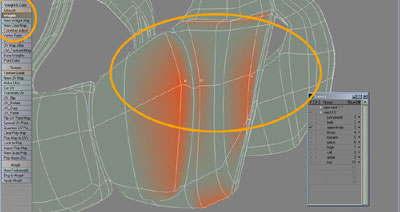
In MODELER use W in the bottom right corner. Set the mode to SUBPATCH WEIGHT in the dialog box.
Go to MAP and choose WEIGHTS then in POINT mode (use space bar) pick the points you want to edit and slide the mouse left and right. If you are in WEIGHT SHADE MODE (e.g. Your model is GREEN) you will see the area around the point change to RED or BLUE depending on how much you slide each way.

A lot of the modeling was done by laying down a set of point and then joint them up, four at a time into polygons (select four points and hit Keyboard ‘P’. Then manipulate the polygons or points into the correct position in the required viewport. Often I would select a line of points, press ‘T’ to MOVE. Move the points into a new position and use COPY and PASTE. This copies the points into the new position and I move the original points back. I then make new polygons with the new point. The benefit of this method is that it keeps the points in the same alignment as the initial points in which every viewport you were using. If you create new points they start in position ‘0` in the selected viewport and need moving to align with other point.

Some of the key points (or Golden nuggets of info) I was thinking about during modeling and some things I’ve learnt along the way:

-Name every little part of the model as you go (Q) and use a hierarchy. Eg. A pipe of the arm would be:- left.arm.forearm.pipe1. This is SO improtant for modeling and texturing
-Model a new part for the model on a new foreground layer with the rest of the model in a background layer.
-When mirroring anything to make a symettrical object make sure the shared points are lined up on the X axis or you will be in a word of Polygon pain. (Set Value X=0)

-Keeping major body sets (e.g. the left thigh and all it pipes and rings) on separate layer until the end of modelling helps with selecting parts for wight mapping. I did this by accident lol as I wasn’t goint to use bones at first so I kept everything on its own layer.

-Hide parts of the model you aren’t using as there is less chance of screwing something up. ( - to hide, \ to reveal)

-Use Subpatch weighting to keep the poly count down and the edges crisp.

-To create pipes I used an eight sided cylinder that was cut into segments. I started at one end and selected groups of points and moved them, them moved along and moved more etc. etc….I could have used loft of outher ways but I found that this was like modeling in the reasl world and I would bent a pipes whereever I like. I always tweaked with DRAGNET set really high and moved point by point.

4.BONES

When I first started this project I was going to keep each major body part on a separate layer and then animate him using pivots points and parenting the layer part together. For example, the bicep, forearm and hand would each be on its own layer in modeller. I would parent hand-forearm-bicep and animate that way. In practice it turned out that I would have far too many layers for this to be practical and there way no way I could animate the neck hoses in that fashion.
I decided to build a full Skelegon rig and give each body part its own Skelegon (place holder for a bone in Layout). The benefits were that the whole model would be on one layer. I could work out a set of Skelegons that would be able to control the neck and head. It would be a great deal more simple when I got it into Layout.

To build the Skelegon frame I started with a ROOT bone in the small of his back and branched out from it, up and down.


5. WEIGHTING

To get the polygons to follow the BONES you need to WEIGHT them. As I had grouped each of the body parts from the start I simply selected the sets one by one and assigned a weight map to it giving it 100% influence. I made sure that the weight maps were named the same as the relevant BONE so that LAYOUT would know which bone effected which set of Polygons.

The HOSE assembly was different. I decided to leave the hose without any weight maps. I had created a set of neck bones that ran through the centre of the hose assembly and into the head. I added a line of bones up through the left and right shoulder casings. The net effect was that the Hose bones moved the hoses and head and the Shoulder bones stopped the hose bones effecting the shoulders. It didn’t work perfectly as the shoulder bar that runs through the centre of the model (at the top shoulder to shoulder) started to look like it was made of rubber when animated. This was fixed by adding even more bones horizontally through the shoulders.