Demonic Warrior Head
Program(s): Rhinoceros 3D
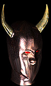
Overview: Here you will use commands such as loft, Sweep 2 rails and more! Modeling heads takes time and once you have a bit of experience in lofting heads it will be very promising and will prove one of the best ways to model faces as well as many other things.
This method is one that takes much practice and time to prefect, but once done it will prove an easier method than Revolving a head or face. Enough chatting, lets get to the technical stuff.
Character Background: This character is from the depths of hell and claims souls for the devil himself. As one of the darkones wrriors he is the meanest of the mean with ultimate knowledge of combat, only the best dare fight him. His Helmet is made from a seemingly rusted but indestructable material that decieves the average person, and his eyes glow with blood.
Concept Sketches: It is always a very wise decision to plan your model ahead of time. With planning comes the ease of drawing profiles and knowing exactly what you want. Even if you are not a great traditional artist it is worth your time anyways.
Modeling In Rhinoceros 3D: Modeling in Rhinoceros is quite different than modeling in 3D Studio Max or Lightwave. With the command line you can access commands faster, and customize the interface if you would like. Take the time to learn the commands and use them, as with time they will evolve into the fastest way to navigate Rhinoceros 3D.
Modeling the Helmet: With this model we will begin by drawing Interpolated splines. Begin with 8 splines for now. In Figure 1 you will see the splines that have been drawn so far. The reason why we use Interpolated splines and not polylines is because we need smooth curves. Polylines only produce straight edges and no smooth, flowing curves.
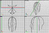
Figure 1
8 Interpolated Splines
----- Now that you have 8 interpolated splines we will now add 8 more splines that are similer to the previous ones. In Figure 2 you will see the new splines in a blue layer, and the previously drawn splines locked in a grey layer. A wise idea would be to mirror or copy the similar splines over instead of drawing completely new ones. Once copied then you should edit their points (CV's) by using ShowCV. To copy use the Copy command, and likewise use the Mirror command to mirror.
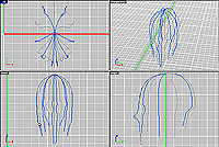 Figure-2
8 New Interpolated Splines
----- With completing the drawing of the splines we can now loft them into a closed surface. Select all of your splines and use the Loft command to access the tool. This should bring up a dialog box with multiple settings. In Figure 3 you see the dialog box as well as the surface quick rendered as a preview.
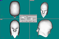
Figure-3
Loft Dialog with Preview
**Note**If the loft comes up looking twisted you will need to select each spline individually going either clockwise, or coutner clockwise, the choice is yours.
Modeling the Neck and Lower Face: As we move on we will now work on the lower face and neck. Both peices will be formed as one surface by lofting splines. This is modeled just about the same way that the helmet was modeled.
----- In Figure 4 you can see there are 8 splines that are separated by color. The splines with the same color have been mirrored over, and therefore are the same splines.
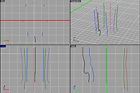
Figure 4
Neck and Lower Head splines, separated by color
----- Once done drawing the splines use the same loft parameters as in the prevous figure. You should end up with a surface such as in Figure 5.
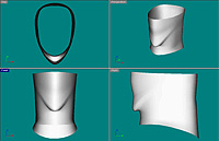
>Figure 5
Neck and Lower Head Lofted
----- Now that you have created both surfaces you can place them together. Next we move oto the horns. To add the horns we will first make small lofted surfaces for the horns to fit into. In Figure 6 you see the splines that have been created to build the surface for the horns to fit into.
These splines were formed by using theCircle command and then dragging them out. You need to scale down the top spline using Scale. You can then loft these splines with the Loftcommand. For this loft use the same parameters as previously done, except make this surface a open loft. Do Not Check the Closed Loft Checkbox.
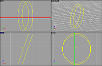
Figure 6
Horn Attachment Splines.
----- In Figure 7 you see the final horn attachment surface. We do not need to payy attention to the small hole in the middle of the surface due to the fact that it will be covered and not visible when finished.
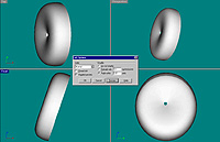
Figure 7
Horn attachment Loft Properties and preview.
----- In Figure 8 you can view the surfaces modeled so far, placed in their positions.
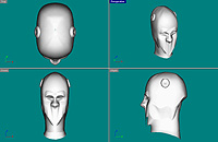
Figure 8
Surfaces Placed into position
Modeling the Horns: As we move on we have to model the horns. We will start the horns by drawing splines as seen in Figure 9. As you see, oe spline is closed, while the other 2 are open.
**Note**The long horn splines are 2 open splines, not one closed spline.
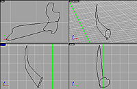
Figure 9
Horn Splines
----- To turn these splines into a surface we will use the Sweep 2 Rails tool. To access the tool use the command Sweep2 and select the 2 open curves. The open curves are the rail curves. Then select the closed spline and press Enter. In Figure 10 you can see the Sweep 2 Rails property's as well as the preview of the surface that is created
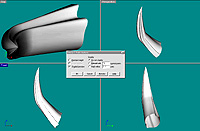
Figure 10
Horn 2 Rail Sweep Dialog, and preview of surface creation
Eyes: The eyes for this model need to fit in the eye sockets of the Helmet. The eyes are nothing but an ellipse that is rotated to fit in the eye sockets. To make an ellipse use the command Ellipse, and drag the ellipse and rotate it using the Rotate command as you see in Figure 11.
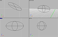
Figure 11
Ellipse for eyes, rotated.
----- Figure 12 shows the ellipses placed in the eye sockets, and the finished model. There is always more you can do with a model, such as make variations in the way that the horns are, which would make the model more realistic.
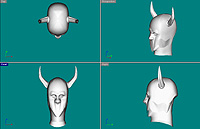
Figure 12
All Objects placed in position
Surfacing: In Rhinoceros 3D there are not many surfacing features other than bump maps, textures, shinyness, and transparency. If you are surfacing in Rhinoceros then you should use a texture with a bump map applied as well. To use a texture and a bump map use the command Texture, you should then see a dialog box to set your texture and bump maps in, as well as transparency, color, and shinyness.
---- Textures are straight forward, but bump maps are used going from black to white, where white is the highest level of bumps, and black is the lowest. Turn your texture into a grayscale image and edit it as needed in a application such as Adobe Photoshop. This will make your final render appear much more realistic. To get a shiny metal surface turn up the shinyness all the way.
---- If surfacing in other applications such as 3D Studio Max there is a large number of things that you could do. Rhinoceros 3D is not meant to be a final renderer.